Industrial Solution Case Studies

Laplace SolutionsLaplace Control SystemsIndustrial Solution Case Studies
[headline style=”big” hedaline_alignment=”headline-align-left” hedaline_subtitle_size=”subtitle-size-small” hedaline_subtitle_position=”bellow” use_underline=”yes” options=”useunderline”]Case Study 1: Controls for Double Headed Stamping Machine and Drive Wind[/headline]

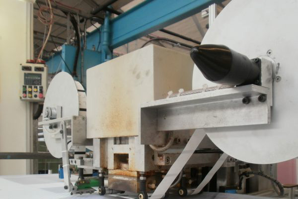
Our client, a dyer of textiles, approached Laplace Industrial Solutions to develop a control system for a replacement textile stamping machine. The clients had an existing machine which would stamp headscarves fed into the machine from large rollers at periodic intervals.

The new machine required the capability to print two stamps onto each headscarf instead of one, and the control system had to allow the choice of stamps in different combinations. The control system also needed to regulate the temperature of the stamp. A control system was also to be provided to operate the drive feeding the cloth into the machine.

  • DATE : 2017
  • CATEGORIES : Industrial Solutions
  • CLIENT : Dyer of textiles
[faq title=”CHALANGE” icon=”Default-check”]Laplace Industrial Solutions sought to improve the existing process through the creation of a  more efficient machine. We sought to do this in three ways: to expand the capacity of the rolls of fabric the machine could handle, to make it possible for the machine to use two stamps instead of one and lastly to increase the rate of output. However, we faced challenges in how best to improve the existing machine to make it stamp scarves at a faster rate, and in how to program a stamping system which allowed a combination of two stamps on a scarf instead of one.[/faq][faq title=”SOLUTIONS” icon=”Default-check”]Increasing the speed of the previous machine was not a viable option because the single motor drive system which pulled the roll of fabric through the machine often left material loose on the stamping head, and would also wind onto the end roller loosely. We resolved this by using a second motor on the feed roller, which provided a back tension on the fabric. The control system was programmed to provide tension at such a level that the material was tight on the stamping head, but not so strong that it would rip. Furthermore, the back tension ensured that the material wound tightly onto the end roller, ensuring that the space which the rolls of fabric occupied was minimised for storage and transit.[/faq][faq title=”RESULTS” icon=”Default-check”]The stamping head was programmed with a matrix which allowed all the combinations of the two stamps which were available. For example, stamps A and B can be combined thus: AA, AB, BA and BB. Sensors were employed to detect the weave on the fabric and hence the correct location for the stamps. The stamper would then press onto the fabric, attaching the insignia using heat.[/faq]
[headline style=”big” hedaline_alignment=”headline-align-left” hedaline_subtitle_size=”subtitle-size-small” hedaline_subtitle_position=”bellow” use_underline=”yes” options=”useunderline”]Case Study 2: Rheological Additives Plant[/headline]

Laplace Industrial Solutions was approached by a major chemicals manufacturer to design software for a rheological additives plant.

Our client specified to optimise the efficiency of the plant through reduction of running costs and man-hours.

  • DATE : 2016
  • CATEGORIES : Industrial Solutions
  • CLIENT : Rheological Additives Plant
[faq title=”CHALANGE” icon=”Default-check”]The technological advancement sought was to increase the output capability of the plant through the programming of its controls. For example, an agitator device was initially operating constantly, but was later programmed to operate for only twenty minutes of every hour, thus saving a considerable amount of energy.[/faq][faq title=”SOLUTIONS” icon=”Default-check”]The uncertainties in this job were the challenges in increasing the output of the plant without altering the additives the plant produces. The additives were all produced using complicated mathematical formulae in the programming, which had to be altered carefully so as to not disrupt the production process.[/faq][faq title=”RESULTS” icon=”Default-check”]The uncertainties were overcome by identifying inefficiencies, and reducing them through the programming of the control systems, thus optimising the plants performance by maximising output and minimising costs and man-hours.[/faq]
[headline style=”big” hedaline_alignment=”headline-align-left” hedaline_subtitle_size=”subtitle-size-small” hedaline_subtitle_position=”bellow” use_underline=”yes” options=”useunderline”]Case Study 1: Remote Control System for High Voltage Switchgear on Windfarm[/headline]

Laplace Energy Solutions was asked to provide a control system which could auto-restore wind turbines in the event of a trip in the electrical systems. The control system had to introduce each turbine onto the national grid in sequence at 60 second intervals. This was to allow the identification of faults in individual turbines, but also to ensure that bringing the windfarm onto the grid provided no large fluctuations in power supplied to the grid.

  • CATEGORIES : Energy Solutions
  • CLIENT : High Voltage Switchgear
[faq title=”CHALANGE” icon=”Default-check”]The company was also asked to provide means of monitoring the windfarm using data logging equipment. A Grid Monitoring Station (GMS) which provided corresponding low voltages for each indicator of performance was developed such that the farm could be monitored using a computer and interface. The monitoring voltages had to reach 80% of the desired output within 50ms, such that readings taken by data recorders were timely and accurate.

Laplace Energy Solutions sought to provide a control system which can act automatically without an operator in the event of a trip in the electrical systems. Prior to the installation of this system, an operator was required to bring the turbines online manually. The new grid management system provided greatly increased accuracy through the decrease in response time of the station.[/faq][faq title=”SOLUTIONS” icon=”Default-check”]We faced a major challenge in developing control panels to withstand harsh climates, and developing a master control panel to the other panels on the site, which had relatively long distances between them. We also faced challenges in programming the panels to enact the auto-restore function described above in the event of point failure.[/faq][faq title=”RESULTS” icon=”Default-check”]These uncertainties were overcome by developing a communication system which utilised fibre optic / copper Ethernet switch technologies capable of operating over long distances (up to 20 km in this case). The system was developed in such a way that communication with the turbines was not interrupted in the event of a single point failure. Remote I/O technologies were sought, sourced and implemented to allow control from the master control panel.[/faq]
[headline style=”big” hedaline_alignment=”headline-align-left” hedaline_subtitle_size=”subtitle-size-small” hedaline_subtitle_position=”bellow” use_underline=”yes” options=”useunderline”]Case Study 2: Combined Heat and Power Plant[/headline]

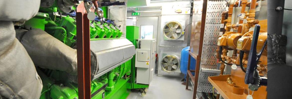
Our client, a prominent Scottish university, wished to reduce its carbon output, and increase energy efficiency. They decided the best way to achieve this was to replace the old existing boiler system and replace it with a more efficient boiler fitted with an inbuilt turbine – a combined heat and power plant (CHP).

  • DATE : 2016
  • CATEGORIES : Energy Solutions
  • CLIENT : Scottish university
[faq title=”CHALANGE” icon=”Default-check”]They decided the best way to achieve this was to replace the old existing boiler system and replace it with a more efficient boiler fitted with an inbuilt turbine – a combined heat and power plant (CHP).[/faq][faq title=”SOLUTIONS” icon=”Default-check”]The CHP works by boiling water to generate steam, which is then used to turn the turbine. The water is then condensed back to hot water to provide heat and hot water to buildings. Laplace Energy Solutions was contracted to provide and install control systems for the CHP, which linked to the Building Management System.[/faq][faq title=”RESULTS” icon=”Default-check”]This project required our expertise in both building management systems and energy controls in order to successfully integrate the CHP with existing systems. The results have seen significant reductions in the carbon footprint of the university, as well as smaller energy bills, due to the greater efficiency of the boilers, and decreased use of grid electricity.[/faq]
[headline style=”big” hedaline_alignment=”headline-align-center” hedaline_subtitle_size=”subtitle-size-small” hedaline_subtitle_position=”bellow” use_underline=”yes” options=”useunderline”]Accreditations[/headline]
[owl_carousel slideshow=”client-logos” item_margin=”30″ navigation=”no” pagination=”no” items=”5″ itemsdesktop=”5″ itemsdesktopsmall=”4″ itemstablet=”3″ itemsmobile=”2″ autoplay=”2000″]